- Team
- Honors Engineering Project, Mission College
- Role
- Designer
- Scope
- Full coilover unit: spring, damper, shock body, adjustment ring, and mounts
- Tools
- Fusion 360, PLA FDM printing
- Methods
- GD&T-based tolerance analysis across three design revisions
- Status
- Smooth, secure adjustment travel achieved after resolving fitment and clearance across three revisions
Objective
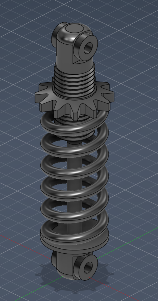
The goal was to reverse-engineer a coilover in Fusion 360 to understand how the individual components come together, how the spring, damper, shock body, adjustment ring, and mounts are shaped, and how they effect each other's range of motion.
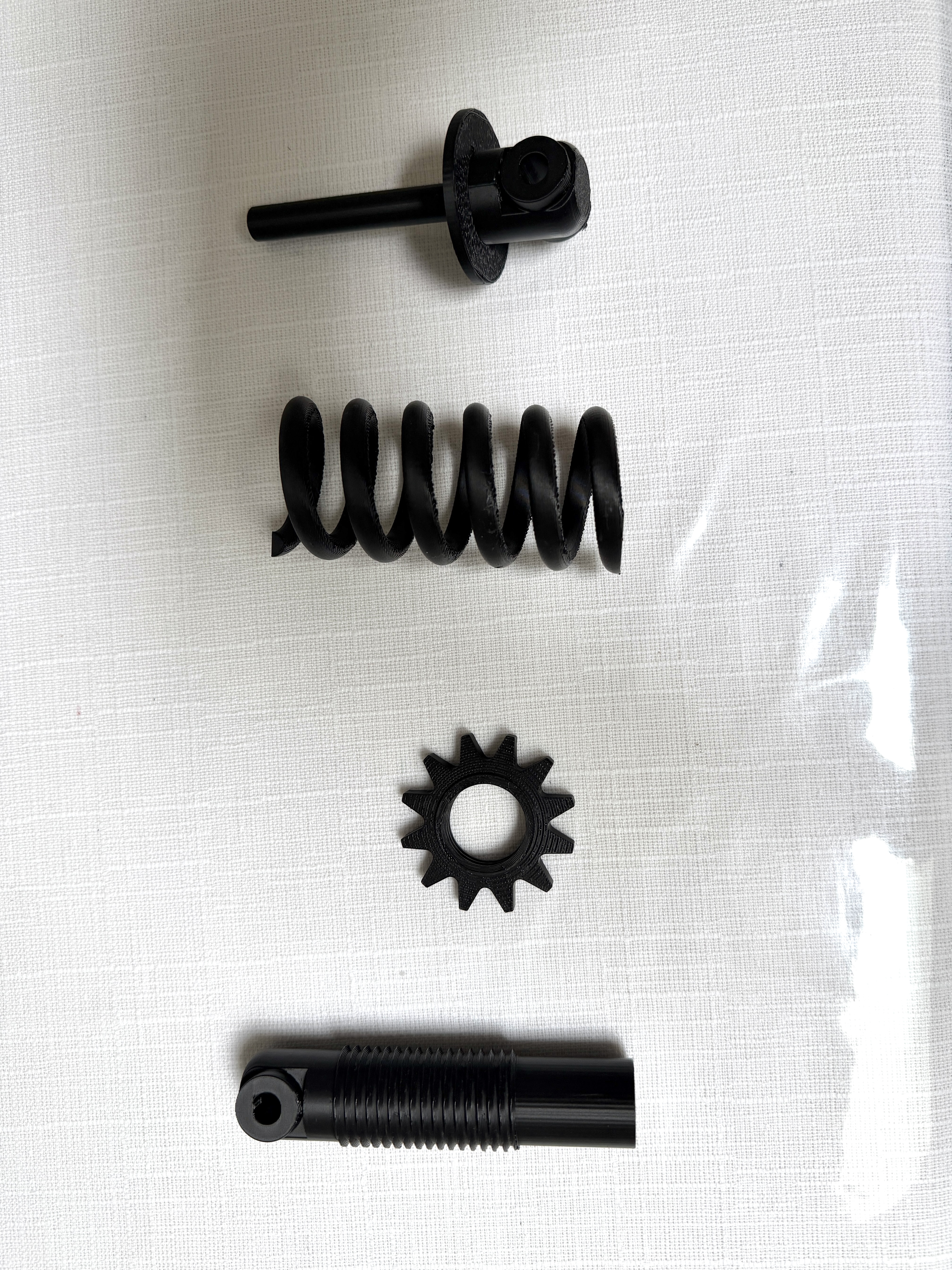
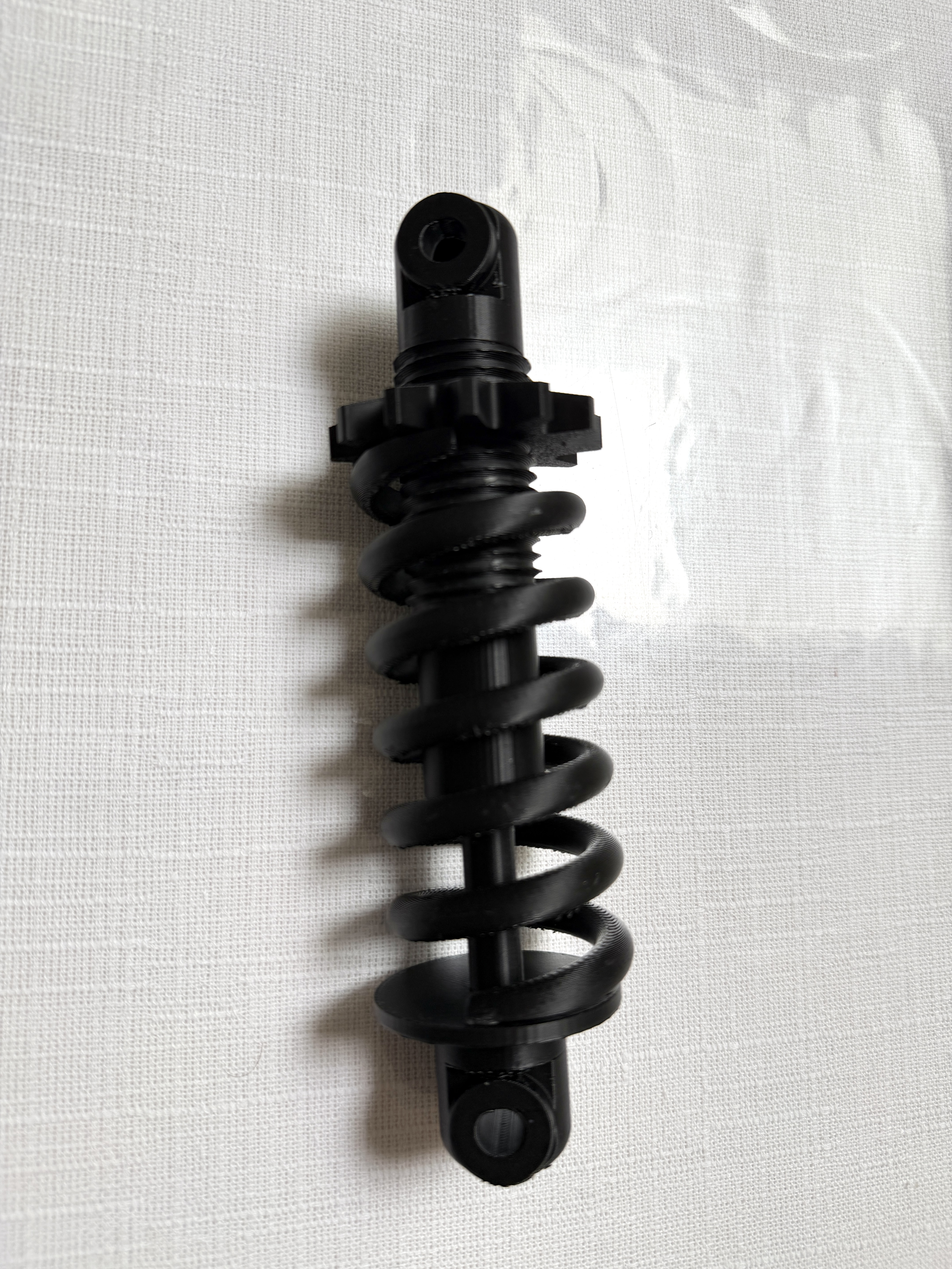
From there, the model had to survive contact with a printer. I wanted to FDM-print the assembly in PLA and get the tolerances right so the result was both dimensionally faithful to the real part and mechanically functional, with the adjustment ring threading smoothly and the assembly holding together securely rather than seizing or rattling.
Approach
I reverse-engineered the coilover from product photos found online and YouTube teardown and modeling tutorials, working part by part in Fusion 360.
I created a makeshift spring travel in Fusion 360 to check that the modeled range of motion behaved the way a real coilover does through compression and rebound, and to confirm the adjustment ring and mounts didn't interfere across that travel before committing anything to the printer.
The tolerances were the real challenge. My first printed revision was too tight and the adjustment ring bound on the threads; loosening the clearance too far on the next pass left the fit sloppy. I tuned the clearances on the threaded and mating surfaces across three revisions until the parts moved smoothly without losing a secure fit.
Result
I ended the project with a complete Fusion 360 model of the coilover and a printed PLA assembly built from it. After three tolerance revisions, the adjustment ring threaded through its full travel smoothly while still holding a secure fit, so the final print was both dimensionally faithful to the reference part and mechanically functional.
The takeaway was less about the finished part and more about the process: working backwards from photos forced me to reason through why each component is shaped the way it is, and working through the iterations gave me a working feel for how much clearance an FDM fit actually needs between moving surfaces.